前回のブログでI2Cでの読み出しのルーチンができたので実際に、RTCと接続して、年月と時刻を呼び出してみます。
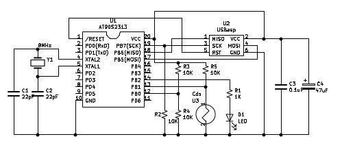
Z8S180とPCA9564との接続は過去プログのこちらの回路となっています。
PCA9564のレジスタはI/O空間の0x80~0x83に配置されます。
注意点として、PCA9564は3.3V動作なので、3.3Vレギュレターで5Vから3.3Vを得ています。
データバス等は5Vトレラントなので、Z8S180にそのまま接続できます。
今回のRTC(RTC-8564NB)の読み方として、16個のレジスタを1度にバッファに読み込み、その後、必要なレジスタをバッファから選択して、表示する方法としました。バッファはプログラムの最後尾に設けていますのでとりあえずは、RAM領域でプログラムを実行します。ここでは開始アドレスをRAM領域である0xa000に設定しました。
まずは、レジスタの定義と呼び出したデータを表示のために、モニターのサブルーチンをコールしているので、そのアドレスの定義を行います。
I2CSTA  .equ    0x80    ;PCA9564 setting adress
I2CTO   .equ    0x80
I2CDAT  .equ    0x81
I2CADR  .equ    0x82
I2CCON  .equ    0x83

putchar         .equ    0x07fe
disp_a_hex      .equ    0x07b1
cr              .equ    0x016d
プログラムの最初で PCA9564のイニシャライズとスレーブアドレス(RTC 0x51)の設定を行います。
続いて、バッファアドレスの設定とカウンター値(レジスターアドレス指定と兼用)の初期設定を行います。
カウンターは0x00から0x0fまで16カウントし、その値がレジスターアドレスとなります。
開始アドレス 0xa000
スレーブアドレス 0x51
バッファアドレス rtc_buff(プログラム最後尾に設定)
カウンター初期値 0x00
.area   TEST (ABS)

.org    0xa000

start:  nop     nop
call    i2c_init                ;i2c init
ld      d,0x51                  ;i2c slave address set d reg
ld      b,0x00
ld      hl,rtc_buff             ;i2c receive data in buff set
カウントのループ内で、レジスターの内容を呼び出していきます。
ループ内のカウンタ
Bレジスタ ループカウント値 0x00~0x0f
HLレジスタ バッファアドレス
呼び出しサブルーチン i2c_readは次の値を設定し、呼び出した後、戻り値をチェックします。
Dレジスタ スレーブアドレス 0x51 (プログラムの最初で設定済み)
Eレジスタ レジスタアドレス 0x00~0x0f 戻り値に指定したレジスタアドレスの読み出した値が入ります。
Aレジスタ 戻り値 正常終了 0x00 エラー時0xff
loop:                                   ;rtc 8564 read register 0x00 to 0x0f
ld      e,b                     ;i2c slave register set e reg
call    i2c_read                ;i2c slave receive call
cp      0xff                    ;a reg 0xff receive err
jr      z,i2c_err_disp
ld      (hl),e                  ;i2c slave data in e reg
inc     hl
inc     b
ld      a,b
cp      0x10                    ;end rtc 8564 register
jr      nz,loop
バッファに対して、必要な位置を指定し、表示に必要なビットをマスクしてから、サブルーチンbcd2を呼び出して、BCD形式を数字2文字に変換して表示させます。
call    cr
ld      a,0x20                  ;Years 20 set
call    bcd2
ld      a,(rtc_buff+0x08)       ;Years ?? i2c read data set
call    bcd2
ld      a,"/"
call    putchar
ld      a,(rtc_buff+0x07)       ;Months ?? i2c read data set
and     0x1f
call    bcd2
ld      a,"/"
call    putchar
ld      a,(rtc_buff+0x05)       ;Days ?? i2c read data set
and     0x3f
call    bcd2
ld      a," "
call    putchar
ld      a,(rtc_buff+0x04)       ;Hours  ?? i2c  read data set
and     0x3f
call    bcd2
ld      a,":"
call    putchar
ld      a,(rtc_buff+0x03)       ;Minutes ?? i2c read data set
and     0x7f
call    bcd2
ld      a,":"
call    putchar
ld      a,(rtc_buff+0x02)       ;Seconds ?? i2c read data set
and     0x7f
call    bcd2
call    cr
ret
サブルーチンbcd2では、BCDの上位4ビットを右4ビットシフトし、マスクしたのち、0x30をORすることにより数字文字に変換して1文字表示します。BCD下位4ビットはシフトせず、以下同様に処理していきます。
bcd2:                                   ;bcd to putchar
push    af                      ; up bcd (7:4)
rlca
rlca
rlca
rlca
and     0x0f
or      0x30
call    putchar                 ;putchar up data
pop     af
and     0x0f                    ;down data (3:0)
or      0x30
call    putchar                 ;putchar down data
ret
実際に実行してみました^^
モニタのバージョンは 0.73です(表示のため、モニタ内部のサブルーチンを読んでいますのでモニタのバージョンが違うと、サブルーチンのアドレスが変わりますので注意してください)
モニタのlコマンドでアセンブルしたHEXコードを呼び込みます。
モニタのCコマンド(call)で実行します。
>c a000 Yes:

2018/09/23 14:54:38
>c a000 Yes:

2018/09/23 14:55:12
>
ちゃんと表示できたようですwww
まとめのソースファイルは次の通りです。
;; z8S180 i/o port on i2c >> i2c RTC  (RTC-8564NB)
;;
;; Z8S180 cpu
;; rom 0000h -- 7fffh
;; ram 8000h -- ffffh
;; External clock 16MHz
;;
;; i2c-bus controller  PCA9564
;;
;;  i/o address
;;      I2CSTA   i/o  0x80(r)
;;      I2CTO    i/o  0x80(w)
;;      I2CDTA   i/o  0x81(r/w)
;;      I2CADR   i/o  0x82(r/w)
;;      I2CCON   i/o  0x83(r/w)
;;
;;
;; assembler
;;  program A000H
;;  data    A000H
;;
;; assemblers  ASxxxx and ASlink V5.10
;; file name rtc07.asm
;; $ asz80 -l -s -o rtc07.asm
;; $ aslink -i rtc07
;; $ monitor l command hex(rtc07.ihx) read

.z180

;; dely timing set in 100uS
D100U   .equ    65      ;;clock in 16MHz set
;D100U  .equ    26      ;;clock in 8MHz set
;D100U  .equ    138     ;;clock in 32MHz set

I2CSTA  .equ    0x80    ;PCA9564 setting adress
I2CTO   .equ    0x80
I2CDAT  .equ    0x81
I2CADR  .equ    0x82
I2CCON  .equ    0x83

putchar         .equ    0x07fe
disp_a_hex      .equ    0x07b1
cr              .equ    0x016d

.area   TEST (ABS)

.org    0xa000

start:  nop     nop
call    i2c_init                ;i2c init
ld      d,0x51                  ;i2c slave address set d reg
ld      b,0x00
ld      hl,rtc_buff             ;i2c receive data in buff set
loop:                                   ;rtc 8564 read register 0x00 to 0x0f
ld      e,b                     ;i2c slave register set e reg
call    i2c_read                ;i2c slave receive call
cp      0xff                    ;a reg 0xff receive err
jr      z,i2c_err_disp
ld      (hl),e                  ;i2c slave data in e reg
inc     hl
inc     b
ld      a,b
cp      0x10                    ;end rtc 8564 register
jr      nz,loop

call    cr
ld      a,0x20                  ;Years 20 set
call    bcd2
ld      a,(rtc_buff+0x08)       ;Years ?? i2c read data set
call    bcd2
ld      a,"/"
call    putchar
ld      a,(rtc_buff+0x07)       ;Months ?? i2c read data set
and     0x1f
call    bcd2
ld      a,"/"
call    putchar
ld      a,(rtc_buff+0x05)       ;Days ?? i2c read data set
and     0x3f
call    bcd2
ld      a," "
call    putchar
ld      a,(rtc_buff+0x04)       ;Hours  ?? i2c  read data set
and     0x3f
call    bcd2
ld      a,":"
call    putchar
ld      a,(rtc_buff+0x03)       ;Minutes ?? i2c read data set
and     0x7f
call    bcd2
ld      a,":"
call    putchar
ld      a,(rtc_buff+0x02)       ;Seconds ?? i2c read data set
and     0x7f
call    bcd2
call    cr
ret

i2c_err_disp:                           ;i2c err disp
call    cr
ld      a,"e"
call    putchar
ld      a,"r"
call    putchar
ld      a,"r"
call    putchar
call    cr
ret
bcd2:                                   ;bcd to putchar
push    af                      ; up bcd (7:4)
rlca
rlca
rlca
rlca
and     0x0f
or      0x30
call    putchar                 ;putchar up data
pop     af
and     0x0f                    ;down data (3:0)
or      0x30
call    putchar                 ;putchar down data
ret

i2c_init:
LD      A,0xff                  ;;Timout Register
out0    (I2CTO),a
ld      a,0x64                  ;;Own Address
out0    (I2CADR),a
ld      a,0x44                  ;;Enable Serial io
out0    (I2CCON),a
call    dely500u                ;; 500u Wite
ld      a,0xc4                  ;;Slave recciver mode
out0    (I2CCON),a              ;; AA=1 ENSIO=1 SI=0
ret

i2c_read:
ld      a,0xe4                  ;;Master Receiver Mode
out0    (I2CCON),a              ;; AA=1 ENSIO=1 STA=1
i2c_r_si01:
in0     a,(I2CCON)              ;; SI=1 ?
bit     3,a
jr      z,i2c_r_si01
in0     a,(I2CSTA)              ;;Poll from transmission finished
cp      0x08
jp      nz,i2c_r_err
in0     a,(I2CDAT)
ld      a,d                     ;set slave addres set a reg
sla     a                       ;carry flag set at write mode
;slave address + write
out0    (I2CDAT),a              ;sleve address set
ld      a,0xc4                  ;;Slave recciver mode
out0    (I2CCON),a              ;; AA=1 ENSIO=1 SI=0

i2c_r_si02:
in0     a,(I2CCON)              ;; SI=1 ?
bit     3,a
jr      z,i2c_r_si02

in0     a,(I2CSTA)              ;;Address+W has been trasimited
cp      0x18                    ;;ACK has been received
jr      nz,i2c_r_err

ld      a,e                     ;;read slave register set
out0    (I2CDAT),a
ld      a,0xc4                  ;;Slave recciver mode
out0    (I2CCON),a              ;; AA=1 ENSIO=1 SI=0
i2c_r_si04:
in0     a,(I2CCON)              ;; SI=1 ?
bit     3,a
jr      z,i2c_r_si04

in0     a,(I2CSTA)              ;;Poll from transmission finished
cp      0x28                    ;ACK has been received
jr      nz,i2c_r_err

ld      a,0xe4                  ;not stop signal is startting
out0    (I2CCON),a              ; AA=1 ENSIO=1 STA=1 STO=0
i2c_r_si05:
in0     a,(I2CCON)              ;SI=1 ?
bit     3,a
jr      z,i2c_r_si05
ld      a,d                     ;read  slave address d reg
scf                             ;set read mode bit0=1
RLA
out0    (I2CDAT),a              ;set slave address
ld      a,0xc4                  ;send data
out0    (I2CCON),a
i2c_r_si06:
in0     a,(I2CCON)
bit     3,a                     ;SI=1 ?
jr      z,i2c_r_si06

in0     a,(I2CSTA)              ;Address+R has been transmitted
cp      0x40                    ;ACK has been received
jr      nz,i2c_r_err

ld      a,0x44                  ;Reset SI And AA bit
out0    (I2CCON),a              ;AA=0 ENSIO=1 STA=0 STO=0
i2c_r_si07:
in0     a,(I2CCON)
bit     3,a                     ;SI=1 ?
jr      z,i2c_r_si07

in0     a,(I2CSTA)              ;Data has been received
cp      0x58                    ;NACK has been returned
jr      nz,i2c_r_err

in0     a,(I2CDAT)              ;Received Data read a reg
ld      e,a
ld      a,0xd4                  ;Generate STOP command
out     (I2CCON),a              ;AA=1 ENSIO=1 STA=0 STO=1

i2c_stop_loop:
in0     a,(I2CCON)
bit     4,a                     ;STO=0 ?
jr      nz,i2c_stop_loop
in0     a,(I2CSTA)
cp      0xf8                    ;reset or STOP command
jr      nz,i2c_r_err
xor     a
ret
;
i2c_r_err:
ld      a,0xff
ret

dely500u:                               ;; 500uS dely
push    bc
ld      b,5
dd5:    call dely100u
djnz    dd5
pop     bc
ret

dely100u:                               ;; 100uS dely
push    bc
ld      b,D100U
l100u:  djnz    l100u
pop     bc
ret

rtc_buff:
.ds     16
prog_end:
.end