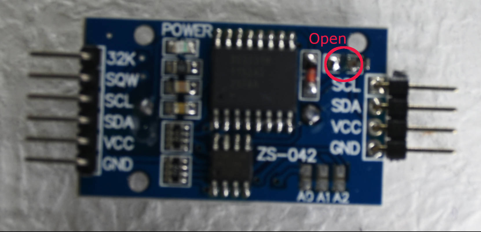
C言語(SDCC)を使用して、今回はZ80+SIO+PIO+PCA9564PWでのI2Cデバイスを使用してRTC(DS3231)、温度・湿度のLCD表示プログラムを作成したいと思います。
回路図は、Z80+SIO+PIOにPCA9564PWの回路を追加しました。
PCA9564PWのI/Oアドレスは、0x8c~0x8fに設定しました。
必要なソフトを作成していきます。
まずは、mycrt0.asmですが、これは、TMPZ84C015と同一です。
    .module crt0
    .globl  _main


    ;; Ordering of segments for the linker.

    .area   _CODE


    .area   _DATA


    .area   _CODE
init::

    call    _main
    ret


    .area   _DATA
アセンブルして、mycrt0.relを得ます。
$ asz80 -l -s -o mycrt0.asm時間稼ぎのルーチンsleep.asmを作成します。
今回は、クロックとして8.000MHzに調整しています。
;;  uint8_t sleep(uint16_t)
;;  Z80 CPU
;;  8.000MHz clock sleep(0x0001) = 1mS


_sleep::

    ld  hl, #0x0002
    add hl, sp
    ld  e,  (hl)
    inc hl
    ld  d,  (hl)
loop1:
    ld  b,  #163
loop2:  nop
    nop
    nop
    nop
    nop
    nop
    nop
    nop
    nop
    djnz    loop2

    dec de
    ld  a,d
    or  e
    jr  nz, loop1

    ld  hl, #0x0000

    ret
アセンブルして、sleep.relを得ます。
$ asz80 -l -s -o sleep.asmPCA9564PW をイニシャライズするi2c_init.asmを作成します。
;;     Z80+SIO+PIO void i2c_init(void)
;;
;;     PCA9564 Initialize
;;
I2CSTA  .equ    0x8c    ;PCA9564 setting adress
I2CTO   .equ    0x8c
I2CDAT  .equ    0x8d
I2CADR  .equ    0x8e
I2CCON  .equ    0x8f

_i2c_init::
        LD      A,0xff                  ;;Timout Register
        out    (I2CTO),a
        ld      a,0x02                  ;;Own Address
        out    (I2CADR),a
        ld      a,0x44                  ;;Enable Serial io
        out    (I2CCON),a

        ld  b,  #82                 ;;500uS wait
loop:   nop
        nop
        nop
        nop
        nop
        nop
        nop
        nop
        nop
        djnz    loop

        ld      a,0xc4                  ;;Slave recciver mode
        out    (I2CCON),a              ;; AA=1 ENSIO=1 SI=0
        ret
アセンブルしてi2c_init.relを得ます。
$ asz80 -l -s -o i2c_init.asmi2c読み込みルーチンi2c_read.asmを作成します。
;;     Z80+SIO+PIO uint8_t  i2c_read(uint8_t,uint8_t,uint16_t *)
;;
;;     i2c read
;;     i2c address,length,buff address
;;
;;
I2CSTA  .equ    0x8c    ;PCA9564 setting adress
I2CTO   .equ    0x8c
I2CDAT  .equ    0x8d
I2CADR  .equ    0x8e
I2CCON  .equ    0x8f

_i2c_read::
        ld  hl, #0x0002
        add hl, sp

        ld      a,0xe4                  ;;Master Receiver Mode
        out     (I2CCON),a              ;; AA=1 ENSIO=1 STA=1
i2c_r01:
        in      a,(I2CCON)              ;; SI=1 ?
        bit     3,a
        jr      z,i2c_r01
        in      a,(I2CSTA)              ;;Poll from transmission finished
        cp      0x08
        jr      nz,i2c_r_err
        in      a,(I2CDAT)
        ld      a,(hl)                  ;set slave addres set a reg
        sla     a                       ;carry flag set at write mode
        set     0,a                     ;slave address + read
        out     (I2CDAT),a              ;sleve address set
        ld      a,0xc4                  ;;Slave recciver mode
        out     (I2CCON),a              ;; AA=1 ENSIO=1 SI=0

i2c_r02:
        in      a,(I2CCON)              ;; SI=1 ?
        bit     3,a
        jr      z,i2c_r02

        in      a,(I2CSTA)              ;;Poll from transmission finished
        cp      0x40
        jr      nz,i2c_r_err

        inc     hl                      ;set length >> b reg
        ld      b,(HL)

        inc     hl                      ;set buff  >> de reg
        ld      e,(hl)
        inc     hl
        ld      d,(hl)
        push    de
data_read:
        ld      a,b
        cp      0x01
        jr      z,data_read_end
        ld      a,0xc4                  ;;Slave recciver mode
        out    (I2CCON),a               ;; AA=1 ENSIO=1 SI=0
i2c_r03:
        in      a,(I2CCON)              ;; SI=1 ?
        bit     3,a
        jr      z,i2c_r03

        in      a,(I2CSTA)              ;;Poll from transmission finished
        cp      0x50
        jr      nz,i2c_r_err

        in      a,(I2CDAT)              ;;read data Areg is I2CDAT
        ld      (de),a
        inc     de
        dec     b
        jr      data_read
data_read_end:
        ld      a,0x44                  ;;Slave recciver mode
        out    (I2CCON),a               ;; AA=1 ENSIO=1 SI=0
i2c_r04:
        in      a,(I2CCON)              ;; SI=1 ?
        bit     3,a
        jr      z,i2c_r04
        in      a,(I2CSTA)              ;;Poll from transmission finished
        cp      0x58
        jr      nz,i2c_r_err
        in      a,(I2CDAT)              ;;read data Areg is I2CDAT
        ld      (de),a
        ld      l,0x01
        jr      i2c_stop

i2c_r_err:
        ld      l,0x00
i2c_stop:

        ld      a,0xd4                  ;Generate STOP command
        out     (I2CCON),a              ;AA=1 ENSIO=1 STA=0 STO=1

i2c_stop_loop:
        in      a,(I2CCON)
        bit     4,a                     ;STO=0 ?
        jr      nz,i2c_stop_loop
        in      a,(I2CSTA)
        cp      0xf8                    ;reset or STOP command
        jr      nz,i2c_stop_err
    pop hl
        ret


i2c_stop_err:
        pop     hl
        ld      l,0x00  ;return 0x00
        ret
アセンブルして、i2c_read.relを得ます。
$ asz80 -l -s -o i2c_read.asmi2c読み込みルーチンi2c_write.asmを作成します。
;;     Z80+SIO+PIO uint8_t i2c_write(uint8_t,uint8_t,uint16_t *)
;;
;;     i2c write
;;     i2c address,length,buff address
;;
I2CSTA  .equ    0x8c    ;PCA9564 setting adress
I2CTO   .equ    0x8c
I2CDAT  .equ    0x8d
I2CADR  .equ    0x8e
I2CCON  .equ    0x8f

_i2c_write::
        ld  hl, #0x0002
        add hl, sp

        ld      a,0xe4                  ;;Master Transmitter Mode
        out     (I2CCON),a              ;; AA=1 ENSIO=1 STA=1
i2c_w01:
        in      a,(I2CCON)              ;; SI=1 ?
        bit     3,a
        jr      z,i2c_w01
        in      a,(I2CSTA)              ;;Poll from transmission finished
        cp      0x08
        jp      nz,i2c_w_err
        in      a,(I2CDAT)
        ld      a,(hl)                  ;set slave addres set a reg
        sla     a                       ;carry flag set at write mode
                                        ;slave address + write
        out     (I2CDAT),a              ;sleve address set
        ld      a,0xc4                  ;;Slave recciver mode
        out     (I2CCON),a              ;; AA=1 ENSIO=1 SI=0

i2c_w02:
        in      a,(I2CCON)              ;; SI=1 ?
        bit     3,a
        jr      z,i2c_w02

        in     a,(I2CSTA)               ;;Poll from transmission finished
        cp      0x18
        jr      nz,i2c_w_err

        inc     hl                      ;set length >> b reg
        ld      b,(HL)
        inc     hl                      ;set buff  >> de reg
        ld      e,(hl)
        inc     hl
        ld      d,(hl)
data_write:
        ld      a,(de)                  ;; write data Areg is I2CDAT
        out    (I2CDAT),a
        ld      a,0xc4                  ;;Slave recciver mode
        out    (I2CCON),a               ;; AA=1 ENSIO=1 SI=0
i2c_w03:
        in     a,(I2CCON)               ;; SI=1 ?
        bit     3,a
        jr      z,i2c_w03

        in     a,(I2CSTA)               ;;Poll from transmission finished
        cp      0x28
        jr      nz,i2c_w_err
        inc     de
        djnz    data_write
        ld      l,0x01
        jr      i2c_stop

i2c_w_err:
        ld      l,0x00
i2c_stop:

        ld      a,0xd4                  ;Generate STOP command
        out     (I2CCON),a              ;AA=1 ENSIO=1 STA=0 STO=1

i2c_stop_loop:
        in      a,(I2CCON)
        bit     4,a                     ;STO=0 ?
        jr      nz,i2c_stop_loop
        in      a,(I2CSTA)
        cp      0xf8                    ;reset or STOP command
        jr      nz,i2c_stop_err
        ret


i2c_stop_err:
        ld      l,0x00                  ;return 0x00
        ret
アセンブルして、i2c_write.relを得ます。
$ asz80 -l -s -o i2c_write.asmアドレスサーチi2c_addr.asmを作成します。
;;     Z80+SIO+PIO uint8_t i2c_addr(uint8_t)
;;
;;     i2c address search
;;     address is return is ack=1  nack=0
;;
I2CSTA  .equ    0x8c    ;PCA9564 setting adress
I2CTO   .equ    0x8c
I2CDAT  .equ    0x8d
I2CADR  .equ    0x8e
I2CCON  .equ    0x8f

_i2c_addr::
        ld  hl, #0x0002
        add hl, sp

        ld      a,0xe4                  ;;Master Receiver Mode
        out     (I2CCON),a              ;; AA=1 ENSIO=1 STA=1
i2c_a01:
        in      a,(I2CCON)              ;; SI=1 ?
        bit     3,a
        jr      z,i2c_a01
        in      a,(I2CSTA)              ;;Poll from transmission finished
        cp      0x08
        jp      nz,i2c_r_err
        in      a,(I2CDAT)
        ld      a,(hl)                  ;set slave addres set a reg
        sla     a                       ;carry flag set at write mode
                                        ;slave address + write
        out     (I2CDAT),a              ;sleve address set
        ld      a,0xc4                  ;;Slave recciver mode
        out     (I2CCON),a              ;; AA=1 ENSIO=1 SI=0

i2c_a02:
        in      a,(I2CCON)              ;; SI=1 ?
        bit     3,a
        jr      z,i2c_a02

        in      a,(I2CSTA)              ;;Poll from transmission finished
    ld  l,a

        ld      a,0xd4                  ;Generate STOP command
        out     (I2CCON),a              ;AA=1 ENSIO=1 STA=0 STO=1

i2c_stop_loop:
        in      a,(I2CCON)
        bit     4,a                     ;STO=0 ?
        jr      nz,i2c_stop_loop
        in      a,(I2CSTA)
        cp      0xf8                    ;reset or STOP command
        jr      nz,i2c_r_err
        ret


i2c_r_err:
        xor     a           ;return nack 0x00
        ld      l,a
        ret
アセンブルして、i2c_addr.relを得ます。
$ asz80 -l -s -o i2c_addr.asmprintf実行のためにputchar.asmを作成します。
;;   Z80+SIO+PIO vido putchar(uint8_t)
;;
SIOAD   .equ    0x84        ;SIO A-CH DATA REG
SIOAC   .equ    0x85        ;SIO A-CH CONTL REG

_putchar::
    ld  hl, #0002
    add hl, sp
putchar01:
    in  a,  (SIOAC);
    bit 2,  a
    jr  z,  putchar01
    ld  a,  (hl)
    out (SIOAD),    a
    ld  hl, #0000
    ret
アセンブルして、putchar.relを得ます。
$ asz80 -l -s -o putchar.asmc言語でアドレスサーチのブロブラムを作成、i2cアドレスをサーチします。
//  I2C Address Search (PCA9564)

#include <stdio.h>
#include <stdint.h>


extern  void    i2c_init(void);
extern  uint8_t i2c_addr(uint8_t);


int main(){

    uint8_t i, j, addr;
    i2c_init();
    printf("I2C Address Search (PCA9564)\n");
    printf("Addr 0 1 2 3 4 5 6 7 8 9 a b c d e f\n");
    for (i = 0; i <= 0x7; i++) {
        printf("  %2x ", i*0x10);
        for (j = 0; j <= 0xf; j++) {
            addr = i * 0x10 + j;
            switch(i2c_addr(addr)){
                case 0x18:                  //addr+W >> ACK
                    printf("%2x",addr);
                    break;
                case 0x20:                  //addr+w >> NACK
                    printf("- ");
                    break;
                case 0x68:                  //Master
                    printf("M ");
                    break;
                default:
                    printf("er");
             }
        }
        printf("\n");
    };
    return(0);
}
コンパイルして、hexファイルを作成ます。
$ sdcc -mz80 --out-fmt-ihx --code-loc 0xa000 --no-std-crt0 -o i2c_addr_main.ihx mycrt0.rel i2c_addr_main.c i2c_init.rel i2c_addr.rel putchar.relモニターlコマンドで読み込み実行してみます。(LCD等はi2cに接続しておきます。)
>c a000 y:
I2C Address Search (PCA9564)
Addr 0 1 2 3 4 5 6 7 8 9 a b c d e f
   0 - M - - - - - - - - - - - - - -
  10 - - - - - - - - - - - - - - - -
  20 - - - - - - - 27- - - - - - - -
  30 - - - - - - - - - - - - - - - -
  40 - - - - - - - - - - - - - - - -
  50 - - - - - - - 57- - - - - - - -
  60 - - - - - - - - 68- - - - - - -
  70 - - - - - - - - - - - - - - - -

>
上記のようにI2Cアドレスが確認出来たら準備OKです。
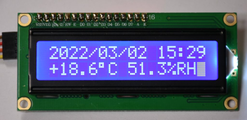
RTC(DS3231)、温度・湿度のLCD表示プログラムを作成します。
今回1部、分の値が00~39分までになっていたので修正しました。
//  I2C(PCA9564) rtc(DS3231) temp,hum(AM2321) LCD(i2c) Display

#include <stdio.h>
#include <stdint.h>

extern  void    i2c_init(void);
extern  uint8_t i2c_read(uint8_t,uint8_t,uint16_t *);
extern  uint8_t i2c_write(uint8_t,uint8_t,uint16_t *);
extern  void sleep(uint16_t);

void i2c_lcd_init(void);
void lcd4bitwrite(uint8_t command);
void lcd8bitwrite(uint8_t command);
void data_lcd4bitwrite(uint8_t command);
void data_lcd8bitwrite(uint8_t command);

const uint8_t   i2c_lcd_addr = 0x27;

int main(){

    uint8_t tmp_addr=0x5c;
    uint8_t rtc_addr=0x68;

    uint8_t len=8;
    uint8_t out_buff[8];
    uint16_t *buff = out_buff;
    uint8_t data_set=0x00;

    uint8_t mesg1[16];
    uint8_t mesg2[16];

    uint8_t tenmetu=0x01;
    uint8_t data_addr = 0x00;
    uint16_t temp,hum;

    int8_t i;

    i2c_init();

    i2c_lcd_init();

    while(1){                                           // main loop
        data_set = 0x00;                                //rtc read
        i2c_write(rtc_addr,1,&data_set);
        i2c_read(rtc_addr,len,buff);
        mesg1[0] = 0x32;    // 2
        mesg1[1] = 0x30;    // 0
        mesg1[2] =(out_buff[6] >>4) | 0x30;             //years
        mesg1[3] =(out_buff[6] & 0x0f) | 0x30;
        mesg1[4] = 0x2f;  //
        mesg1[5] =((out_buff[5] & 0x1f) >>4) | 0x30;    //months
        mesg1[6] =(out_buff[5] & 0x0f) | 0x30;
        mesg1[7] = 0x2f;  //
        mesg1[8] =((out_buff[4] & 0x3f) >>4) | 0x30;    //days
        mesg1[9] =(out_buff[4] & 0x0f) | 0x30;
        mesg1[10] = 0x20;  //
        mesg1[11] =((out_buff[2] & 0x3f) >>4) | 0x30;   //hours
        mesg1[12] =(out_buff[2] & 0x0f) | 0x30;
        mesg1[13] = 0x3a;  //
        mesg1[14] =((out_buff[1] & 0x7f) >>4) | 0x30;   //minutes 2022/4/10 Fix
        mesg1[15] =(out_buff[1] & 0x0f) | 0x30;         // 0x3f >> 0x7f

       data_set = 0x80;
        lcd8bitwrite(data_set);                         //x80 (1line top address)
        for (i=0; i<16 ;i++){
            data_lcd8bitwrite(mesg1[i]);
//          printf("%c\n",mesg1[i]);
        }


        data_addr = 0x00;                               //AM2321 Wake up
        i2c_write(tmp_addr,1,&data_addr);
        sleep(1);
        out_buff[0] = 0x03;                             //4 bytes temperature and humidity
        out_buff[1] = 0x00;
        out_buff[2] = 0x04;
        i2c_write(tmp_addr,3,buff);
        sleep(2);
        i2c_read(tmp_addr,len,buff);                    // get temperature and humidity


        hum=((uint8_t)out_buff[2] << 8) | (uint8_t)out_buff[3];                 //humidity
        temp=((((uint8_t)out_buff[4]) & 0x7f) << 8) | (uint8_t)out_buff[5];     //temperature
//      printf("temp=%1x,%1x,%1x\n",temp/100,(temp%100)/10,(temp%100) %10);

        if ((out_buff[4] & 0x80) == 0x80){              //temperature Upper 7-bit polarity
            mesg2[0]= 0x2d;                             // -
        }else{
            mesg2[0]= 0x2b;                             // +
        }

        mesg2[1] = ((temp/100) | 0x30) & 0x3f;          //temperature Tenth digit
        mesg2[2] = (((temp%100) /10) | 0x30 ) & 0x3f;   //temperature 1st digit
        mesg2[3] = 0x2e;                                // .
        mesg2[4] = (((temp%100) %10) | 0x30 ) & 0x3f;   //temperature 1st decimal place
        mesg2[5] = 0xdf;                                // do
        mesg2[6] = 0x43;                                // C
        mesg2[7] = 0x20;                                // space
        mesg2[8] = ((hum/100) | 0x30 ) & 0x3f;          //humidity Tenth digit
        mesg2[9] = (((hum%100) /10) | 0x30 ) & 0x3f;    //humidity 1st digit
        mesg2[10] = 0x2e;                               // .
        mesg2[11] = (((hum%100) %10) | 0x30 ) & 0x3f;   //humidity 1st decimal place
        mesg2[12] = 0x25;                               // %
        mesg2[13] = 0x52;                               // R
        mesg2[14] = 0x48;                               // H

        if(tenmetu == 0x01){                            // Blinking
            mesg2[15] = 0x20;
        }else{
            mesg2[15] = 0xff;
        }
        tenmetu = tenmetu ^ 0x01;

        data_set = 0xc0;
        lcd8bitwrite(data_set);                             //x80 + 0x40(2 line top address)
        for (i=0; i<16;i++){
            data_lcd8bitwrite(mesg2[i]);
//          printf("%2x\n",mesg2[i]);
        }

        sleep(500);                                         //500mS wait
    }
    return(0);
}

void i2c_lcd_init(void){
        //Display initialization
    uint8_t data_set;

    data_set=0x03;

    lcd4bitwrite(data_set);
    sleep(5);
    lcd4bitwrite(data_set);
    lcd4bitwrite(data_set);
    data_set=0x02;
    lcd4bitwrite(data_set);             //4bit mode
    data_set=0x28;
    lcd8bitwrite(data_set);             //function set 4bit bus,2 line ,1 line=8
    data_set=0x0c;
    lcd8bitwrite(data_set);             //disp on,under cursor off,block
    data_set=0x01;
    lcd8bitwrite(data_set);             //disp clr
    sleep(2);
    data_set=0x06;
    lcd8bitwrite(data_set);             //disp address incrmant on,disp shift off
    data_set=0x02;
    lcd8bitwrite(data_set);             //cursor home set
    sleep(2);
}
void lcd4bitwrite(uint8_t command){
    command <<= 4;
    command |= (uint8_t)0b00001000;
    command &= (uint8_t)0b11111000;
    i2c_write(i2c_lcd_addr,1,&command);
    command |= (uint8_t)0b00001100;
    command &= (uint8_t)0b11111100;
    i2c_write(i2c_lcd_addr,1,&command);
    command |= (uint8_t)0b00001000;
    command &= (uint8_t)0b11111000;
    i2c_write(i2c_lcd_addr,1,&command);

}
void lcd8bitwrite(uint8_t command){

    uint8_t command2;

    command2 = command;
    command >>= 4;
    lcd4bitwrite(command);
    lcd4bitwrite(command2);
}
void data_lcd4bitwrite(uint8_t command){

    command <<= 4;
    command |= (uint8_t)0b00001001;
    command &= (uint8_t)0b11111001;
    i2c_write(i2c_lcd_addr,1,&command);
    command |= (uint8_t)0b00001101;
    command &= (uint8_t)0b11111101;
    i2c_write(i2c_lcd_addr,1,&command);
    command |= (uint8_t)0b00001001;
    command &= (uint8_t)0b11111001;
    i2c_write(i2c_lcd_addr,1,&command);

}
void data_lcd8bitwrite(uint8_t command){

    uint8_t command2;

    command2 = command;
    command >>= 4;
    data_lcd4bitwrite(command);
    data_lcd4bitwrite(command2);

}
コンパイルします。
$ sdcc -mz80 --out-fmt-ihx --code-loc 0xa000 --no-std-crt0 -o i2c_lcd_rtc_tmp_main.ihx mycrt0.rel i2c_lcd_rtc_tmp_main.c i2c_init.rel i2c_read.rel i2c_write.rel putchar.rel sleep.relLCD上に前回記事と同じように表示されます(無限ルーチンになっているのでモニタには帰ってきません)